Hey there! I’m an air core inductor supplier, and I’ve been in this business for quite a while. One of the questions I get asked a lot is how the equivalent circuit helps in analyzing an air core inductor. Well, let me tell you, it’s a game-changer! Air Core Inductor
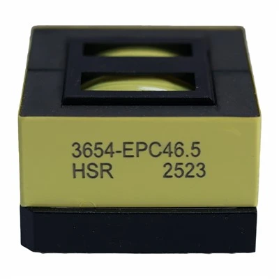
First off, let’s talk a bit about what an air core inductor is. Unlike iron core inductors that use a magnetic core to increase inductance, air core inductors have no core or use a non – magnetic core. This results in lower inductance values but also has some great advantages like no core losses and low distortion at high frequencies. That’s why they’re super popular in applications like radio frequency (RF) circuits, high – frequency filters, and communication systems.
Now, the equivalent circuit is like a simplified model of the real air core inductor. It represents the physical inductor using a combination of ideal electrical components such as resistors, inductors, and capacitors. Why do we need this? Well, real – world air core inductors are complex. They have not only inductance but also resistance due to the wire used and capacitance between the turns of the coil. Analyzing the real device directly can be a real headache, but the equivalent circuit makes things way easier.
Let’s break down the equivalent circuit of an air core inductor. The most basic one consists of an ideal inductor (L), a resistor (R), and a capacitor (C). The ideal inductor represents the self – inductance of the coil, which stores energy in the magnetic field when current flows through it. The resistor accounts for the resistance of the wire. You know, even the best – quality copper wire has some resistance, and this can cause power losses in the form of heat, especially at high currents. The capacitor represents the parasitic capacitance between the turns of the coil. This capacitance can have a big impact on the performance of the inductor, especially at high frequencies.
One of the main ways the equivalent circuit helps is in understanding the frequency response of the air core inductor. In a circuit, different frequencies can behave differently. At low frequencies, the inductive reactance (XL = 2πfL) is relatively small, and the resistance of the wire might be the dominant factor. But as the frequency increases, the inductive reactance goes up, and the inductor starts to act more like an inductor. At very high frequencies, the parasitic capacitance comes into play. The capacitance and the inductance can form a resonant circuit, and at the resonant frequency, the impedance of the inductor can change dramatically.
Using the equivalent circuit, we can calculate the resonant frequency of the air core inductor. The formula for the resonant frequency is fr = 1/(2π√(LC)). By knowing this frequency, we can design circuits that either take advantage of the resonance or avoid it. For example, in some RF circuits, we might want to use the inductor at its resonant frequency to create a band – pass filter. On the other hand, if we’re using the inductor in a power supply circuit, we’d want to avoid resonance because it can cause unwanted oscillations and voltage spikes.
Another benefit of the equivalent circuit is in calculating the impedance of the air core inductor. Impedance is a measure of how much the inductor opposes the flow of alternating current. It takes into account both the resistance and the reactance (inductive and capacitive). The impedance formula for the equivalent circuit is Z = √(R²+(XL – XC)²), where XC = 1/(2πfC). Knowing the impedance is crucial for matching the inductor with other components in the circuit. If the impedance is not matched properly, there can be reflections of the signal, which can lead to a loss of power and reduced performance.
When it comes to designing circuits, the equivalent circuit also helps in predicting the performance of the air core inductor under different conditions. For example, if we want to increase the inductance, we can use the equivalent circuit to analyze how this will affect the resistance and capacitance. We can also see how changes in the physical dimensions of the inductor, such as the number of turns or the diameter of the coil, will impact its electrical properties.
As a supplier, I find the equivalent circuit extremely useful when working with customers. Some customers come to me with specific requirements for their circuits, like a certain inductance value, a maximum impedance at a particular frequency, or a low loss factor. By using the equivalent circuit, I can quickly analyze which of our air core inductors will meet their needs. It also allows me to communicate more effectively with them. I can explain to them why a certain inductor might be a better choice based on its equivalent circuit parameters.
Let’s take an example. Suppose a customer is designing a high – frequency RF amplifier. They need an inductor with a specific inductance value and low resistance at a high frequency. Using the equivalent circuit, I can calculate the impedance of different inductors in our product line at that frequency. I can also analyze the impact of the parasitic capacitance on the performance of the inductor. Based on this analysis, I can recommend the best – suited inductor to the customer, and chances are, they’ll have a much better – performing circuit.
The equivalent circuit also helps in quality control. We use it to test and verify the electrical properties of our air core inductors. During the manufacturing process, we can measure the resistance, inductance, and capacitance of the inductors and compare them with the values predicted by the equivalent circuit. If there are significant differences, it might indicate a problem in the manufacturing process, such as a defect in the wire or an incorrect number of turns.
In conclusion, the equivalent circuit is an invaluable tool for analyzing an air core inductor. It simplifies the complex real – world inductor into a combination of ideal components, which makes it easier to understand its behavior at different frequencies, calculate its impedance, and predict its performance in a circuit. Whether you’re a circuit designer, an engineer, or just someone looking for a high – quality air core inductor, understanding the equivalent circuit can help you make better decisions.
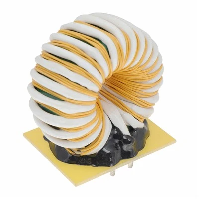
If you’re in the market for air core inductors and need some guidance on which one is right for your project, don’t hesitate to reach out. We’re here to help you find the perfect solution for your needs. Whether you have a specific requirement or just want to learn more about our products, give us a shout. We’d love to start a conversation and see how we can assist you in your next project.
SMD Inductor References:
- "Electronics Fundamentals: Circuits, Devices, and Applications" by Thomas L. Floyd
- "RF Circuit Design" by Chris Bowick
Dongguan Hensiron Electric Co., Ltd.
As one of the most professional air core inductor suppliers in China, we have world-leading production equipment and strong manufacturing capabilities. Please feel free to buy high quality air core inductor made in China here from our factory. Customized orders are welcome.
Address: Building 4, Xinxing Industrial Zone, Wangao Road, Wanjiang Street, Dongguan City, China
E-mail: jessica@dghensiron.com
WebSite: https://www.dghensiron.com/
