Hey folks, thanks for stopping by today. I’m Jake, part of the team here that builds and installs large synchronous motors for all kinds of heavy industrial stuff—think mines, power plants, big chemical processing facilities, that sort of thing. One question I get every single week from new clients and even some engineers I chat with at trade shows is: “What the hell actually goes into commissioning a motor that big? It’s not like plugging in a fridge and flipping a switch, right?” Large Synchronous Motor
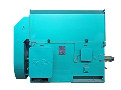
You’re exactly right. A 5,000 horsepower (that’s roughly 3.7 megawatts, for the metric folks out there) synchronous motor isn’t a small appliance. It’s a hunk of precision-engineered steel, copper, and insulation that’s gonna run for 20+ years if you do it right. Mess up the commissioning, and you’re looking at downtime that costs thousands, maybe tens of thousands, of dollars an hour. I’ve seen it happen—client skipped a step, tried to speed things up, burned out a rotor winding before it even turned a single revolution. Not fun for anyone.
So today, I’m walking you through the exact steps we follow every time we commission one of these motors. No fancy jargon that doesn’t mean anything, no cut corners. This is the real deal we use on job sites.
First, let’s get something clear: commissioning doesn’t start the second the motor shows up on the back of a flatbed. It starts way earlier, like two to four weeks before delivery. Wait, why? Because a lot of the issues we run into after unboxing aren’t the motor’s fault—they’re on the customer’s side. For example, if their foundation is off by a quarter-inch, or the power supply they wired up for the motor is 10% under-spec, that’s a problem we can’t fix once the motor’s there.
Phase 0: Pre-Commissioning Site Check (Yeah, We Call It Phase 0, Not Step 1)
We send one of our lead techs out a week before the motor is even scheduled to arrive. What do we check first? The foundation. Large synchronous motors have specific weight and alignment requirements. If the grout (that cement-like stuff that secures the motor to the foundation) isn’t cured properly, or the foundation’s surface is uneven, you’re gonna have vibration issues down the line. We use a laser level to make sure the base is within 0.002 inches per foot of flatness. That’s tiny—think about the thickness of a human hair, basically.
Next up: power system verification. The motor’s not just gonna plug into a regular outlet. It runs on medium voltage—usually 4160V or 13,800V, depending on size. We need to confirm the customer’s transformer and switchgear are rated for the motor’s full load current. We also check that the grounding system is solid—bad grounding is the #1 cause of electrical issues in motors, no joke. We’ll do a ground resistance test to make sure it’s under 5 ohms, the standard for industrial gear.
Then, we check all the ancillary systems that run with the motor: cooling fans, lubrication pumps, control panels. For a synchronous motor, you need excitation systems too—this is the thing that creates the magnetic field in the rotor so the motor can sync up with the power grid. We test the excitation panel’s wiring to make sure there are no loose connections before the motor even gets there. If we skip this, we’re just wasting time once the motor’s unloaded.
Okay, now the motor’s actually here. It’s offloaded, craned into position, and we’re ready to start physically setting it up. That’s Step 1: Mechanical Installation and Alignment.
Step 1: Mechanical Installation & Precision Shaft Alignment
You can’t just set a 20-ton motor on its base and call it good. The motor’s shaft has to line up perfectly with whatever it’s driving—usually a pump, compressor, or generator. If the alignment is off, you get vibration, which wears out bearings way faster, or even cracks the motor shaft. We use two tools for this: dial indicators and a laser alignment system. Dial indicators are good for basic checks, but laser is way more precise for large shafts. We get the alignment to within 0.001 inches axial and 0.002 inches angular. Again, tiny numbers, but critical.
Once alignment is done, we bolt the motor down tight. Then we pump in the grout between the base and the foundation. We let that cure for at least 72 hours—no rushing this. We’ve seen clients cut it to 48, and within a month, the alignment was off so bad they had to tear the whole thing apart. Not worth it.
After grout cures, we do a general mechanical check: open up the motor’s end bells, check that the bearings are properly greased (wait, no—modern synchronous motors often use oil lubrication, not grease, for high load. Got that right), spin the rotor by hand to make sure it moves freely, no rubbing against the stator windings. If the rotor catches on anything, that’s a manufacturing error we need to catch before powering it up.
Step 2: Insulation Testing (The “Don’t Kill It With Electricity” Step)
Large motors have tons of copper windings wrapped in insulation. Over time, insulation can get damaged from shipping, moisture, or just age. Before you hook up power, you need to test that insulation is still good. We use a megohmmeter (we call it a “megger” around the shop, sounds less boring) for this.
What do we test? First, the insulation resistance between the stator windings and the motor frame. For a new motor, that number should be at least 1 megohm per 1000 volts of rated voltage. So a 10,000V motor needs at least 10 megohms. If it’s lower than that, that means there’s moisture or a tiny flaw in the insulation. We might need to bake the windings to dry them out before proceeding.
We also do a polarization index test, which is just a longer insulation test—we leave the megger connected for 10 minutes, instead of 1. The ratio of the 10-minute reading to the 1-minute reading tells us if the insulation is healthy, not just surface-level good. If that ratio is below 2, we have a problem. No exceptions here. I’ve had a motor come in from a remote mine that had insulation resistance of 0.5 megohms because it sat in the rain during shipping. We baked the windings for 48 hours, and it passed—if we’d skipped that, we would’ve burned out the windings on first power-up.
Also, we test the excitation system’s insulation here too. The rotor winding is smaller, but just as important. If that insulation breaks down, you can lose the magnetic field the motor needs to sync.
Step 3: Control & Excitation System Testing (Making It Do What It’s Supposed To)
Synchronous motors don’t just start like induction motors. They need an excitation system to build up rotor magnetism before they connect to the line. If you skip this step, the motor will “chatter” and never reach full speed, or even damage the stator.
First, we test all the control circuits: the push buttons, the overcurrent relays, the temperature sensors (the ones that tell you if the motor is running too hot). We simulate a start signal from the control panel to make sure it sends the right signal to the excitation system. We also test the emergency stop—this is a big one, if that doesn’t work, someone can get hurt.
Then, we test the excitation system itself. We apply a low voltage to the excitation winding and measure the current to make sure it matches the manufacturer’s specs. We also test the “pull-in” current—this is the amount of excitation needed to get the rotor to lock into sync with the power grid. If that’s off, the motor won’t run at full speed. We do this with the motor unloaded first, so if something goes wrong, we’re not risking damage to the load.
Step 4: No-Load Testing (Let The Motor Run… Without Driving Anything)
Now we’re ready to power the motor up, but not connect it to the load yet. No-load testing is to make sure the motor itself runs smoothly, no electrical issues, no weird sounds.
First, we do a “excitation buildup” test. We ramp up the excitation current slowly, watching the rotor speed climb. A synchronous motor’s speed is locked to the grid frequency—so if the grid is 60Hz, the motor should run at 1800 RPM (for a 4-pole motor, common size for large units) or 900 RPM for 8-pole. If it’s running slower, that means it’s not synced up, and we have to adjust the excitation. We watch for vibration here too—use a vibration meter to make sure it’s under 0.1 inches per second, the industry standard for smooth operation.
We also measure the stator current and power factor during no-load. For synchronous motors, you can adjust power factor with the excitation. A properly tuned motor should run at near-unity power factor (around 0.95-0.98) when loaded, but we confirm that the excitation system can adjust that as needed. If the current is way higher than the manufacturer’s no-load current, that means there’s a winding issue we missed.
We run no-load for at least an hour, monitoring temperature—bearing temperature, stator winding temperature, cooling system temps. If any temperature spikes, we shut it down and check. One time, a motor ran 20 degrees hotter than it should have during no-load, turned out a cooling fan was wired backwards. Fixed that, no big deal, but we caught it before loading it.
Step 5: Load Testing (Putting It To Work)
This is the moment we’ve been waiting for: connect the motor to the actual load (pump, compressor, whatever it’s driving) and test it under real working conditions. We gradually increase the load from 25% to 50% to 75% to 100%, waiting 15 minutes at each level to take measurements.
What do we measure here? Shaft speed (to make sure it stays synced, no slip), stator current, power factor, vibration, and temperature. We check for any unusual noise—grinding, humming, that sort of thing. A faint magnetic hum is normal, but any loud clanking is not.
We also test the overload protection at 110% of the motor’s rated current. The overcurrent relay should trip within a set time, per design. If it doesn’t, that’s a problem for when the motor draws extra current during peak demand.
Once we hit 100% load, we run it for at least 4 hours. That’s not arbitrary—we want to make sure the motor runs steadily, no temperature creep, no alignment issues from the load. We keep logs of every reading during this time, so we have a record for the customer for maintenance later.
Wait, there’s one more part to load testing: dynamic testing, if the customer needs it. That’s where we do things like sudden load changes, simulate a power drop, to make sure the excitation system can adjust quickly. We don’t do that on every job, but for critical applications like power plant motors, it’s non-negotiable.
Step 6: Final Documentation & Training
A lot of people think the job ends when the motor runs, but that’s not true. We leave the customer with a full set of commissioning reports: alignment readings, insulation test results, no-load and load test data, excitation system settings. We also train the customer’s maintenance team on basic checks: how to read the temperature sensors, how to test the ground connection, what to do if the motor trips.
We also leave a list of recommended maintenance tasks for the first year, like monthly bearing checks and annual insulation testing. Large motors are low-maintenance, but you have to do the small stuff to keep them running.
Now, I know some of you are thinking, “Can’t I just skip some of these steps to get the motor running faster?” Look, I get it—down time is expensive. But I’ve seen way too many clients cut a corner here, miss a tiny issue, and end up with 3 days of downtime to fix a problem that would’ve taken 10 minutes to catch during commissioning.
If you’re in the market for a large synchronous motor, especially for a critical application, don’t just buy a motor and hope for the best. Work with a team that knows the commissioning process, that’s gonna show up and check every single step, not just hook it up and run it.

If you’re looking to spec a new synchronous motor or need help with commissioning for an existing unit, reach out to our team. We’ve worked with mines, power plants, chemical processors, and all kinds of industrial facilities, and we can walk you through every step from pre-commissioning to long-term maintenance. Don’t gamble with your equipment—let us make sure it’s installed and commissioned right the first time.
Explosion Proof Motor References
- IEEE Std. 112-2017, IEEE Standard Test Procedure for Polyphase Induction Motors and Generators
- NEMA MG 1-2022, Motors and Generators, National Electrical Manufacturers Association
- “Commissioning Guidelines for Large Synchronous Machines” from the Electrical Apparatus Service Association (EASA), 2021
Xian Putai Electric Motor Equipment Co., Ltd.
Xian Putai Electric Motor Equipment Co., Ltd. is one of the most professional large synchronous motor manufacturers and suppliers in China, also supports customized service with low price. Welcome to buy advanced large synchronous motor in stock here from our factory. If you have any enquiry about quotation, please feel free to email us.
Address: Haibo Guangchang Fengcheng Nine Road Economical & Technological Development District Xi’an City Shaanxi Province – China
E-mail: sales@putaimotor.com
WebSite: https://www.putaimotor.com/
